
In this blog I will go through best practices for design integration applications. Wisdom that I have garnered through projects, MuleSoft recommendations, reviews of MuleSoft project and discussions with MuleSoft specialists.
General
- Connector retry/Until successful/retry APIs should be present for all connections / connectors. This is an obvious one networks, and the internet have occasional disconnections. So you should always retry a few times before giving up and abandoning the operation.
- High volume processes should be coupled with MuleSoft Batch framework and appropriate queuing mechanisms wherever necessary. This to make the processing faster and more reliable but be cautious about which queuing infrastructure you are using. VM queues are mostly queuing in memory which might cause out of memory issues.
- Exceptions are logged to an agreed upon location. Best of course is to a ticketing system like ServiceNow or through regular logging and having log mentoring system like Splunk to collect the logs and issue waring. Refrain from utilizing Emails to send errors to support teams. Things get messy with emails and sometime tracking is lost.
- Long-running processes should provide a way to inspect progress to date. Usually this is done through sending notification through a hookup API or pushing the progress to the logs. But it important to have a way to see that so far 60% of the data load has been processed
- Processes are designed to be loosely coupled and promote reuse where possible. Adopt microservices sensibly not to small and not large.
-
Adopt the MuleSoft API-Led connectivity approach sensibly. Aha, this is a tricky and controversial one. Many novice Developers/Architects just follow the 3-layer API-Led pattern (System API, Process API, Experience API) religiously without thinking of the consequences. There are times when the three tiers are required other times you only need two tiers only. For example if the integration is a batch job that picks up files or records from a DB and push them to Salesforce. Then you only need System API Layer and Integration layer (no need for experience or process API layers). See below a summary of eh API Led Connectivity Approach.
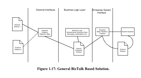
- System APIs should expose a canonical schema (project or domain scope) when there is an identified Canonical Schema for the project, domain, or organization scope. Do not just replicate the source system API removing any system specific complexities. I have seen implementation where the developers just replicated the source system API just removing the authentication for source system. This meant spending 1-4 weeks to develop test an API that removes Source System Authentication with another authentication system for the system API. As a Manager or from the client side why did we spend 4 weeks = 160 hrs at $200 per hour = 32K to develop something that is does not add 32K worth value and would cost us in the future to maintain. The reason we use a Middle wear like MuleSoft to implement integrations is to make it easy to replace system and reduce vendor dependencies. For example, if we are integrating Salesforce, SAP, Workday, and Shopify for example. If after say 2 years the crop decided to replace SAP with Dynamics AX. Now if the System API for SAP exposed SAP API with just minor modifications for authentication. Then the Dynamics AX system API does the same the all the process or integration applications would have to be changed and recoded. This is the main reason that Enterprise Service Bus had such a bad reputation. Because of bad implementations. As I wrote in my Book “BizTalk the Practical Course” http://www.lulu.com/shop/moustafa-refaat/biztalk-the-practical-course/paperback/product-4661215.html Yes I know this MuleSoft but theory is the same. It is like Quick Sort in C#, Java, C++, Scala, Python. You are still implementing “Quick Sort” same algorithm same theory different tool. Read the full discussion in the preview Page 35.
- When creating a canonical schema stick to the project/domain scope and do not try to create a generic canonical schema for the whole organization.
I cannot stress this enough, while MuleSoft promotes the Three-Tire structure and Application API network, it does not always make sense to use this approach in all situations. Strive to design the integration architecture to be: –
-
Easy to maintain
-
As modular as possible
-
Any components that can be reused should be isolated into its own library or application
The MuleSoft API-led connectivity approach
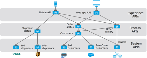
API-led connectivity is a methodical way to connect data to applications through a series of reusable and purposeful modern APIs that are each developed to play a specific role – unlock data from systems, compose data into processes, or deliver an experience. API-led connectivity provides an approach for connecting and exposing assets through APIs. As a result, these assets become discoverable through self-service without losing control.
- System APIs: In the example, data from SAP, Salesforce and ecommerce systems is unlocked by putting APIs in front of them. These form a System API tier, which provides consistent, managed, and secure access to backend systems.
- Process APIs: Then, one builds on the System APIs by combining and streamlining customer data from multiple sources into a “Customers” API (breaking down application silos). These Process APIs take core assets and combines them with some business logic to create a higher level of value. Importantly, these higher-level objects are now useful assets that can be further reused, as they are APIs themselves.
- Experience APIs: Finally, an API is built that brings together the order status and history, delivering the data specifically needed by the Web app. These are Experience APIs that are designed specifically for consumption by a specific end-user app or device. These APIs allow app developers to quickly innovate on projects by consuming the underlying assets without having to know how the data got there. In fact, if anything changes to any of the systems of processes underneath, it may not require any changes to the app itself.
Defining the API data model
The APIs you have identified and started defining in RAML definitions exchange data representations of business concepts, mostly in JSON format. Examples are:
-
The JSON representation of the Policy Holder of a Motor Policy returned by the “Motor Policy Holder Search SAPI”
-
The XML representation of a Quote returned by the “Aggregator Quote Creation EAPI” to the Aggregator
-
The JSON representation of a Motor Quote to be created for a given Policy Holder passed to the “Motor Quote PAPI”
-
The JSON representation of any kind of Policy returned by the “Policy Search PAPI”
All data types that appear in an API (i.e., the interface) form the API data model of that API. The API data model should be specified in the RAML definition of the API. API data models are clearly visible across the application network because they form an important part of the interface contract for each API.
The API data model is conceptually clearly separate from similar models that may be used inside the API implementation, such as an object-oriented or functional domain model, and/or the persistent data model (database schema) used by the API implementation. Only the API data model is visible to API clients in particular and to the application network in general – all other forms of models are not. Consequently, only the API data model is the subject of this discussion.
Enterprise Data Model versus Bounded Context Data Models
The data types in the API data models of different APIs can be more or less coordinated:
-
In an Enterprise Data Model – often called Canonical Data Model, but the discussion here uses the term Enterprise Data Model throughout – there is exactly one canonical definition of each data type, which is reused in all APIs that require that data type, within all of Acme Insurance
-
E.g., one definition of Policy that is used in APIs related to Motor Claims, Home Claims, Motor Underwriting, Home Underwriting, etc.
-
In a Bounded Context Data Model several Bounded Contexts are identified within Acme Insurance by their usage of common terminology and concepts. Each Bounded Context then has its own, distinct set of data type definitions – the Bounded Context Data Model. The Bounded Context Data Models of separate Bounded Contexts are formally unrelated, although they may share some names. All APIs in a Bounded Context reuse the Bounded Context Data Model of that Bounded Context
-
E.g., the Motor Claims Bounded Context has a distinct definition of Policy that is formally unrelated to the definition of Policy in the Home Underwriting Bounded Context
-
In the extreme case, every API defines its own API data model. Put differently, every API is in a separate Bounded Context with its own Bounded Context Data Model.
Abstracting backend systems with System APIs
System APIs mediate between backend systems and Process APIs by unlocking data in these backend systems:
-
Should there be one System API per backend system or many?
-
How much of the intricacies of the backend system should be exposed in the System APIs in front of that backend system? In other words, how much to abstract from the backend system data model in the API data model of the System APIs in front of that backend system?
General guidance:
-
System APIs, like all APIs, should be defined at a granularity that makes business sense and adheres to the Single Responsibility Principle.
-
It is therefore very likely that any non-trivial backend system must be fronted by more than one System API
-
If an Enterprise Data Model is in use, then
-
the API data model of System APIs should make use of data types from that Enterprise Data Model
-
the corresponding API implementation should translate between these data types from the Enterprise Data Model and the native data model of the backend system
-
-
If no Enterprise Data Model is in use, then
-
each System API should be assigned to a Bounded Context, the API data model of System APIs should make use of data types from the corresponding Bounded Context Data Model
-
the corresponding API implementation should translate between these data types from the Bounded Context Data Model and the native data model of the backend system
-
In this scenario, the data types in the Bounded Context Data Model are defined purely in terms of their business characteristics and are typically not related to the native data model of the backend system. In other words, the translation effort may be significant
-
-
If no Enterprise Data Model is in use, and the definition of a clean Bounded Context Data Model is considered too much effort, then
-
the API data model of System APIs should make use of data types that approximately mirror those from the backend system
-
same semantics and naming as backend system
-
but for only those data types that fit the functionality of the System API in question backend system often are Big Balls of Mud that cover many distinct Bounded Contexts
-
lightly sanitized e.g., using idiomatic JSON data types and naming, correcting misspellings, …
-
expose all fields needed for the given System API’s functionality, but not significantly more ◦ making good use of REST conventions
-
The latter approach, i.e., exposing in System APIs an API data model that basically mirrors that of the backend system, does not provide satisfactory isolation from backend systems through the System API tier on its own. In particular, it will typically not be possible to “swap out” a backend system without significantly changing all System APIs in front of that backend system – and therefore the API implementations of all Process APIs that depend on those System APIs! This is so because it is not desirable to prolong the life of a previous backend system’s data model in the form of the API data model of System APIs that now front a new backend system. The API data models of System APIs following this approach must therefore change when the backend system is replaced. On the other hand:
-
It is a very pragmatic approach that adds comparatively little overhead over accessing the backend system directly
-
Isolates API clients from intricacies of the backend system outside the data model (protocol, authentication, connection pooling, network address, …)
-
Allows the usual API policies to be applied to System APIs
-
Makes the API data model for interacting with the backend system explicit and visible, by exposing it in the RAML definitions of the System APIs
-
Further isolation from the backend system data model does occur in the API implementations of the Process API tier
MuleSoft Application Modularization
Mule allows you to run applications side-by-side in the same instance. Each Mule application should represent a coherent set of business or technical functions and, as such, should be coded, tested, built, released, versioned and deployed as a whole. Splitting particular functions into individual applications allows a coarse-grained approach to modularity and is useful when keeping elements of your application running while others could go through some maintenance operations. For optimum modularity:
Consider what functions are tightly interrelated and keep them together in the same Mule application: they will form sub-systems of your whole solution.
-
Establish communication channels between the different Mule applications: the VM transport will not be an option here, as it can’t be used across different applications. Prefer the TCP or HTTP transports for synchronous channels and JMS for asynchronous ones
